| | Home | | Site Map | | Trenches | | Links | | Konundrums | |
| | Downloads | | Forum | | Tech | | Toolbox | | Personnel | |
| You are here: | HOME > | TECH INDEX > | LAROKE How To #2 |
| NOLOGIES NIQUES |
|
|
HOW TO Number 2:Attaching a BNC Connector to thinnet cable (Page 2) |
|||||
|
Prepare the end of the cable with the cable stripper tool. Leave yourself a few extra feet of cable length for mistakes. If you get a bad connector, you'll be able to cut it off and try again. Setting up the cable stripper may require some trial and error adjustment. I've found that not all BNC connectors are created equal - close but not 100 percent. The length of exposed inner insulation band may vary a small amount. 1/8 inch is about right as a starting point (your mileage may vary).
If the cable stripper does not completely do its job, you may have to clean up the cable end with an X-acto knife or needle file. Care counts here. The center conductor should not be nicked, nor should any of the braided shielding be exposed - the most difficult part of this operation is to strip the shielding without damaging the inner insulation band.
|
|
|
|
LAROKE Microcomputer Consultants Issued Saturday July 24, 1999 copyright © 1996-1999 LAROKE Microcomputer Consultants all rights reserved
|
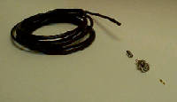 The components consist of the coax cable and the connector. The cable I use is from Radio Shack and labeled "TANDY WIRE AND CABLE E111378A TYPE RG-58U 20 AWG CL2 75 deg (UL)". The important thing to remember is that 10Base-2 network segments use Type RG-58 with 50 ohm impedence. It is also a good idea to make a length of test cable and try it out between a couple of computers on the system before actually going through the trouble of pulling cable through wall and ceiling spaces. You don't want to do all that hard work only to find you've got the wrong cabling! The connector itself consists of three parts: the connector itself, the center pin, and the crimp barrel.
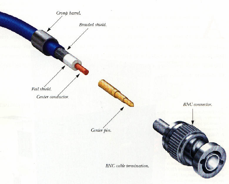
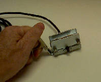 With the type of cable stripper shown, leave about 1/4 inch of cable sticking out the front of the stripper. You then rotate the stripper about the cable until the two layers of insulation and the shielding are cut through to their proper depths.
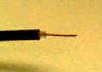 The stripped cable should look something like this. The center conductor is about 1/2 inch long (it will be cut to fit). The exposed portion of the inner insulation band is about 1/8 inch and the braided shielding between the two insulation bands has been cut back cleanly to the same length as the outer insulation band.